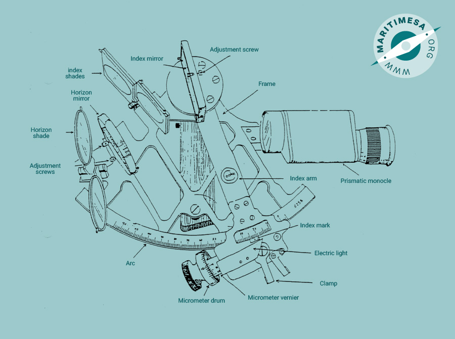
Parts of the sextant.
The sextant is made up of the following parts:
- The frame.
- The handle.
- The telescope or monocle.
- The rising piece.
- The arc.
- The index arm.
- The clamp.
- The worm and rack.
- The micrometer drum.
- The micrometervernier.
- Electric light.
- The index mirror.
- The index mirror clips.
- The index mirror (first) adjustment screw.
- The index mirror shades.
- The horizon mirror.
- The horizon mirror clips.
- The horizon mirror (second) adjustment screw.
- The horizon mirror (third) adjustment screw.
- The horizon mirror shades.
The frame. This is either of rigid metal construction or moulded plastic. It incorporates three legs upon which the sextant rests when in the horizontal position. The upper side of the frame is referred to as the Plane of the instrument. The curved, lower part of the frame is referred to as the lower limb of the instrument.
The handle. The handle is fitted with a button switch and has a compartment for batteries to power the electric light on the index arm.
The telescope or prismatic monocle. This is used to enlarge the observed object and to make accurate observations easier. The telescope usually has a magnification of 4 X and a field of view of 5°. The monocle on the other hand has a magnification of 6 X and a field of view of 8½°. Higher magnification is desirable when observing vertical sextant angles of distant shore objects to obtain a clearer view of the sun’s lower limb when taking sights. A wide field of view is important when trying to locate stars which are not easily found because of the apparent size.
The rising piece. The telescope or monocle is attached to the frame by and adjustable slide or rising piece which is fitted with a milled head quick release screw. By adjusting the rising piece the telescope is brought closer to or further from the frame. This adjustment alters the area of the horizon mirror viewed through the telescope and hence alters the brilliance of the reflected image.
The arc. If the sextant is of the metal variety, the arc will be constructed of a thin strip of metal which has a low co-efficient of expansion. It is “let in” flush with the “lower limb” of the sextant and is graduated from 0° to 120° “on” the arc and from 0° to -5° “off” the arc.
The index arm. The index arm is mounted on a circular base plate and is free to rotate on a central axis underneath the index mirror. The arrow of the index arm is known as the index mark.
The clamp. By exerting finger pressure, the clamp disengages or unclamps the index arm from the gearing cut into the lower limb of the sextant. The index arm can then be moved to the required angle. On releasing pressure, the index arm is automatically clamped in position.
The worm and rack. The worm is an endless tangent screw which engages with the rack or gearing which is cut into the lower limb of the sextant. Exerting pressure on the quick release clamp disengages the worm from the rack and allows the index arm to be moved.
The micrometer drum. While whole degrees are read directly from the arc, minutes of arc are read from the micrometer drum. Turning the micrometer drum screws the worm along the rack and permits fine adjustment of an observed angle or altitude.
The micrometervernier. The micrometervernier has five or six graduations which correspond to 0.2’ or 10” of arc respectively. Minutes of arc are read off the micrometer drum opposite the vernier index mark. Seconds or decimals of a minute of arc are read where one of the vernier graduations lines up perfectly with one of the minute graduations on the micrometer drum.
The electric light. The light bulb is contained in a special holder so arranged that the light illuminates the arc, micrometer drum and vernier. It is operated by pressing the button(s) in the handle and is useful for taking twilight sights.
Index mirror. The index mirror is rectangular in shape and set in a frame attached to the moveable index arm. When properly adjusted it should be perpendicular to the plane of the instrument. Its purpose is to reflect light to the horizon mirror.
The index mirror clips. These are spring clips that hold the mirror to its frame.
Index mirror adjustment screw (first adjustment). This is an adjustment screw situated on the centre line of the mirror. By adjusting the screw the mirror is pushed against the spring clips and moved to the perpendicular position.
The index mirror shades. These shades are made of high quality optical glass and are neutral or coloured light filters. They are used to reduce the intensity of the sun’s reflected image and to protect the eyes. There are normally four shades.
The horizon mirror. This mirror receives the image from the index mirror and reflects it back to the observer through the telescope. It can be either a rectangular or circular mirror held in an appropriate frame. As the horizon mirror occupies only half the space enclosed by its frame, the observer is able to see both the reflected image and the horizon at the same time. Like the index mirror it needs to be perpendicular to the plane of the instrument and parallel to the index mirror when the index arm is set to zero.
The horizon mirror clips. These are spring clips holding the horizon mirror in its frame.
The horizon mirror adjustment screw (second adjustment). This adjustment screw is situated on the centre line of the horizon mirror. It may be at the top or bottom of the mirror, depending on its design. It is used to adjust the horizon mirror to the perpendicular position.
The horizon mirror adjustment screw (third adjustment). The adjustment screw is located on the edge of the mirror and is used to adjust the horizon mirror parallel to the index mirror when the index arm is set to zero.
The horizon mirror shades. These are used to reduce the intensity of a brightly lit horizon and are similar to the index mirror shades. Two or three horizontal shades are normally fitted.