Radar really comes into its own during poor visibility. The techniques that will be described in this section applies to such circumstances. Whilst most modern marine radars now have a computer built in (ARPA – Automatic Radar Plotting Aid), which provides many more features than the older sets, the basic principles of blind pilotage remain. With the old PPI’s (planned position indicators – circular radar display screen) one needs a rotatable PPI cursor (circular Perspex attachment to the PPI), engraved with parallel (index) lines and designed to overcome parallax error. The technique used with these parallel lines is called “parallel index”. It was important that the centre spot of the PPI should remain in the centre and that the ship’s heading marker should remain correctly lined up.
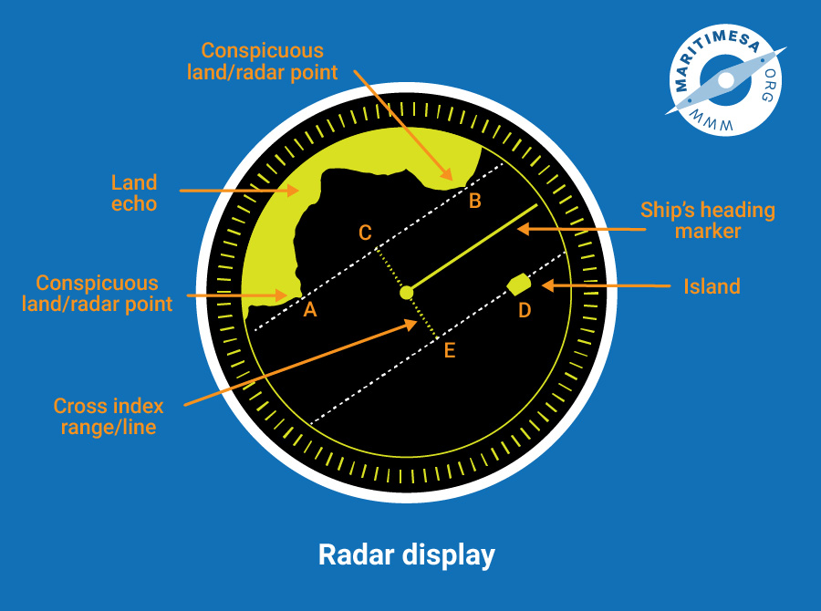
- Maintaining a specified track. If it is desired to pass a specified distance, OE, off a radar- conspicuous object, D, set the index lines parallel to the intended track, draw the parallel through E in chinagraph pencil (or an erasable overhead projector marker) and steer a course so that the relative track of D remains on parallel index line DE. Points A and B could also be used in a like fashion. The distance OX is called the cross index range (CIR) as is the distance OE.

Maintaining a specified track.
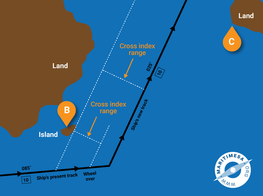
- Altering course. In the figure below, the ship is approaching harbour on a selected track parallel to the coast. In order to enter it needs to alter course to port. On the chart are two conspicuous points which are also conspicuous on radar. Point B is a small island situated close to the shore on the eastern side of the entrance while point C is a headland marking the western side of the entrance. Both B and C appear to be suitable marks on which the course alteration can be made. If C is chosen, the moment at which course should be altered will be determined by radar bearing, whereas if B is chosen it will depend on the radar range.
From this it is clear that, at the moment the alteration is made, the chosen object should be as near to 90° from the future track as possible. In this case B should be selected. On the chart draw lines parallel to the new course through the edge of B and through the plotted position of “wheel over” (allowing for the turning radius of the vessel). The first line will give you the cross index range for commencing your turn. The second line will give you your new track when the turn is completed. Now plot the two parallel index lines on the PPI cursor at the scale to be used and rotate the cursor to the intended new track. When the echo of B cuts the furthest line, put the wheel over and commence the turn. The echo of B will then appear to follow the dotted track and eventually coincide with the nearest line being the new track. Subsequently the right edge of C may be used to continue the approach on the new course.

Altering course.
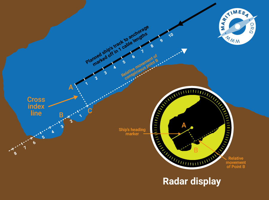
- Anchoring. If one wanted to anchor in the position indicated in the sketch below, the following procedure would be carried out. The approach course (track) should be drawn on the applicable chart with the anchor position clearly marked. The track should be marked back at one cable distances from the anchor position.
On the chart a radar conspicuous point should be selected, in this case a projection of land (object B). A line is drawn through this point, parallel to the approach track and the perpendicular drawn from A to this line at C. AC is the cross index range and BC is called the “dead range”. The PPI cursor is then prepared as indicated in the sketch on the display scale to be used, with the parallel index line drawn at the cross index range from the centre. The dead range is then marked, also the intervals of cable to the limit of the range of the cursor. The cursor is then rotated so that the index lines are parallel to the approach track. As the ship approaches, the distance to go is indicated on the cursor by the position of the echo of B.
Anchoring.
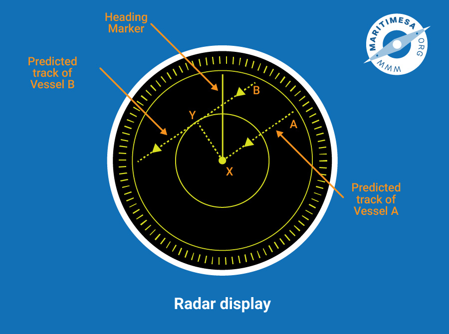
- Anti-collision. Another use of parallel index occurs in anti-collision work, both in fog and in good visibility. If the parallel index is aligned with a few successive plots of another ship, the risk of collision can be rapidly assessed. If the relative track of the other ship passes through the centre of the PPI, then the ship is on a collision course. In the figure below, ship A is on a collision. Ship B will pass clear. The closest point of approach (CPA) of B is the point Y and XY is the cross index range.

Anti-collision.


